Showing posts with label Ford. Show all posts

Thursday, May 2, 2019

Common Merkur issues and recommended fixes

Found this elsewhere on the Internet (on that classic DIY website hosting company angelfire of all places) but thought it was worth reposting since my custom domain name isn't going away any time soon, Blogger isn't going to go away any time soon, and neither am I. Well, I guess that's what we all think. Ha ha.

So, here it is, the common issues and common first things to try to resolve them on your Merkur XR4Ti.

Driveshaft torsional dampener or guibo
  • It is not a U-joint. It must be in perfect shape with no cracks. The driveshaft must have zero degrees runout when checked at the guibo or it will deteriorate quickly. 
Rear brake lights
  • The ground wire which is brown in the connectors will corrode and short out the adjacent connectors. Remove the bad ground wire in the light panel and solder a wire onto the light bulb holder that is directly connected to this ground wire. 
Valve cover gasket
  • Recommended: The Ranger gasket works well and is reinforced with steel so that if the top end is getting pressurized it will help to stop the oil from leaking out. 
  • Also works: Use the blue silicone rubber Fel Pro gasket to eliminate oil leaks onto the exhaust manifold.  
Leaking sunroof
  • Blow out the drain lines that connect to the pan in the roof. If this doesn't help then you need to fix either the drain hoses or the drain pan. 
Bad window switches
  • Take apart the switches and clean them or buy good used ones. 
No rear view mirror
  • Buy the correct Ford rear-view mirror attachment kit. 
Poor performance
  • Usually ignition parts. 
Yellowed headlights
  • Normal polish and refurbish. Polish the plastic lenses with a plastic polish. 
Broken hazard flasher
  • Only real option is to find a used one in good shape. 
Broken hatch lock
  • Find a good used one in good shape. 
Wetness in the car after it rains
  • Either fix the sunroof drain tubes or the tail light gaskets. 
Inconsistent idle
  • Clean the ENTIRE intake tract until all carbon is gone. Replace all the gaskets. Set the base timing, base idle, then the TPS. 
Heated seats don't work
  • Fix the small wire in the back of the seat. Both heaters are hooked together, If one doesn't work then the other won't work. 
Hard leather seats
  • Use a good saddle soap multiple times to restore the moisture into the leather. Maintain the leather regularly. Window tint will help stop the sun damage to the seats. 
Gauges don't work
  • Usually a cold solder on the daughterboard. This is located on the back of the instrument cluster. 
Oil blowing out of the engine
  • The Ford PCV valve is not adequate to hold the boost from entering the crankcase. Add a good one way valve in line with the stock valve to stop the boost from entering the crankcase. A brass brake booster valve will work well for this. Also the dipstick is not calibrated correctly. Put in a new filter and five quarts of oil. Run the engine for one minute and shut it off. Let the car sit for 30 minutes and check the oil level. Mark the correct level line on the dipstick with a file mark. 
The buzzer in the dash goes off whenever you step on the gas
  • This probably means that the Wastegate Actuator is bad. Cost: between $50-90 dollars. 
Front end shimmys at different speeds
  • Replace all the front end bushings and balance the wheels and tires as a start. 
Door rattles when it's closed
  • The track may be broken. Very common on the drivers side door. Weld the track back together or find a good used one. 
Bad radio reception
  • The wire that runs to the antenna in the rear decklid glass frequently breaks. Replace it. 
Automatic Transmission leaks
  • The factory cooler is way too small. Replace it with the biggest one you can afford and bypass the one in the radiator. Also the dipstick tube leaks where it goes into the trans. You can fix this by removing it and wrapping it with Teflon tape and reinstalling it. 

Saturday, April 20, 2019

Throwback: MerkMeter Installation Instructions


I happened to acquire one of these recently and had to go digging for the instructions. Given the website has been dead for 15 years, I am reproducing the instructions here for others to benefit. Good luck with your Merkur!

Chris


    MerkMetertm Installation Instructions:   XR4Ti
    Introduction
    Installation is very simple and should easily take less than one hour.  Installation of the MerkMeter basically involves removing the instrument cluster, inserting the meter into the preexisting slot, running a wire (provided) to the computer, and connecting this wire to the oxygen sensor signal wire at the computer wiring harness.  Most of the time required will be spent in removing and replacing the instrument cluster.  

    Please read through these instructions completely once before proceeding.  Although they may appear lengthy, we have just tried to be thorough and not assume any previous experience on the part of the installer.  


    CAUTION: Although the MerkMeter has not been shown in practice to be sensitive to damage caused by static discharge, it does have a semiconductor component.  As such, care should be taken to handle the MerkMeter outside its protective anti-static bag as little as possible.  Under no circumstances should it be handled while an electrical source is connected.


     Tools Required:
    • Philips head screwdrivers
    • 7mm nut driver or socket
    • Pliers
    • 19 mm open-end wrench (For late model cars with cruise control)


    Step One:  Remove Instrument Cluster
    Note: The step order outlined here may be slightly different than that described elsewhere, but is the easiest procedure we have found in removing many XR4Ti instrument clusters.  TIP: Before removing the instrument cluster check for any malfunctioning light bulbs.  Now would be a good time to replace them.  
    1. Remove screw from upper steering column shroud and remove shroud.
    2. Remove three screws from the bottom of the lower steering column shroud and remove the shroud.  Note: One screw is near the steering wheel and two are at the hood release latch.
    3. Remove four screws retaining instrument cluster bezel.  Carefully pull bezel free and remove the panel illumination control and intermittent wiper control rheostats.  TIP: Carefully push these controls out the front of the bezel and disconnect them from their wiring harness by gently pulling on the connector.
    4. Remove four screws holding instrument cluster to dash and pull cluster towards the steering wheel.  Do this gently and only far enough to allow your hand to reach behind the left side of the cluster.
    5. Remove the turbo boost gauge vacuum line by pulling it free of the nipple on the back of the instrument cluster.  TIP:  If this hose is old, it may be necessary to twist it a bit to pull it free.  The OE hose frequently develops a leak near the connection with the nipple, so now would be a good time to replace this hose if it is old.
    6. Disconnect the cluster wire harness by gently pulling on the connector.
    7. Locate the speedometer cable connector where it is attached to the back of the instrument cluster.  While pressing on the “button” on the side of the white plastic cable latch, gently pull the cable free of the cluster.  The cable should come free easily without much required force.  TIP: In later model cars equipped with cruise control there is little or no slack in the two-piece speedometer cable.  It will be necessary to disconnect the cable inside the firewall (near the fuse box) using a 19mm wrench.  Only pull the cluster far enough to disconnect the cable as described above.
    8. Remove cluster from dash.


    MerkMetertm Installation Instructions:   XR4Ti
    Step Two:  Configure MerkMeter
    Dot  / Bar Mode


     The MerkMeter can be configured to display in either Dot Mode (one light at a time displayed) or Bar Mode (current reading and all lights below are on).  The MerkMeter is shipped with Dot Mode as the default and is the recommended mode.
    To set the MerkMeter to operate in Bar Mode, install the shorting jumper on J1 (See Figure 1) across BOTH pins.  
    Instantaneous / Dampened Mode
    How quickly the MerkMeter display responds to changes in the output of the oxygen sensor can also be set.  In Instantaneous Mode the MerkMeter will display the voltage changes in the oxygen sensor immediately.  While in Dampened Mode, the MerkMeter will not be as quick to change in response to changes in the oxygen sensor output.  The MerkMeter is shipped with Instantaneous Mode as the default and is the recommended mode. 
    To set the MerkMeter to operate in Dampened Mode, install the shorting jumper on J2 (See Figure 1) across BOTH pins.


    Step Three: Install MerkMeter in Instrument Cluster  

    1. Remove panel insert from the back of the instrument cluster.  Simply squeeze the tab to unlock and slide out the insert blank. (See Figure 2)
    2. Remove the protective paper from the two self-adhesive pads on the MerkMeter.
    3. Carefully slide the MerkMeter into the slot in the back of the instrument cluster with the adhesive pads facing up.  (The side with the electronic components will be on the bottom.)  When properly installed, the three red LEDs will be on the left when viewed from the front.  Be careful not to allow the adhesive pads to stick to the cluster yet.
    1. Continue to slide the MerkMeter into the slot until the display socket of the MerkMeter is securely pressed into the opening and is flush with the front of the panel.
    2. Carefully and firmly press upward on the back of the MerkMeter to allow the adhesive pads to stick to the two small plastic tabs at the top of the slot while ensuring the MerkMeter remains in the proper position.  NOTE: The meter may also be secured using the large white wire tie.  The wire tie should be routed through the hole on the MerkMeter and the eyelet on the tie then secured to the hole just above the mounting slot with a suitable screw (not included).  It is easiest to place the tie through the MerkMeter hole first and only tighten it slightly.  Then the screw should be inserted through the eyelet and threaded into the hole a couple turns.  If you keep as much slack as possible in the tie, you can rotate the MerkMeter and insert it into the mounting slot.  When the meter is in position, the tie can be slowly cinched down as the slack is carefully worked out of the tie. The screw should then be threaded the rest of the way into the hole.  Do not over-tighten the tie or the screw.
    3. Remove the nuts from the electrical supply studs on the back of the cluster indicated in Fig 2 as “Power” and “Ground” using a 7 millimeter nut driver.
    4. Attach the RED wire to the stud indicated in Fig 2 as “Power” and secure it with one of the nuts.
    5. Place the BLACK wire on the stud indicated in Fig2 as “Ground”.  Also place the tab adaptor used to secure the BLACK ground extension wire onto the same stud.  Attach wire and tab with the remaining nut.
    6. Attach the spade connector on the BLACK ground extension wire to the chassis grounding screw on the dash support bracket directly behind the instrument cluster. Loosen the screw a few turns, slide the spade connector under the screw and retighten the screw.  NOTE: This extra ground wire is needed since the instrument cluster ground Ford provided via the stock wiring harness is inadequate.
    7. Check again that all wire connections are correct. Ensure that the ring connectors are not in contact with any other nearby studs.  Be sure the chassis ground screw is tight and all wires are secure.
    8. Remove the sound-deadening panel from beneath the glove box.
    9. The male connector end of the oxygen sensor signal wire should be carefully routed from the cluster, through the dash opening, and down and under the center console to the passenger side foot well area.  (It may also be possible to route the wire down and through directly behind the radio.)  A length of coat hanger wire may assist in fishing the wire through. 
    10. Attach the female connector on the extension signal wire to the GREEN wire on the MerkMeter.  Attach the grounding wire to the tab adaptor installed on the cluster ground stud.  The instrument cluster should be temporarily placed in its mounting hole or on the dash.


    Step Four:  Connect Oxygen Sensor Signal Wire
    Note 1: The EEC-IV computer receives the input from the oxygen sensor via Pin 29 on the computer wiring harness.  The oxygen sensor signal wire should be DARK GREEN with a dashed PURPLE stripe but might vary.  Verify the proper wire by tracing it to Pin 29 on the connector.  DO NOT RELY ON THE WIRE COLOR ONLY.  Connecting the MerkMeter to the incorrect wire will cause it to malfunction. A wrong connection may damage the MerkMeter, the computer, and/or some other part of the vehicle
    Note 2: The splice connector supplied with the MerkMeter is an Insulation Displacement Connector (IDC).  This means the connector will pierce the wire’s insulation to make an electrical connection.  If the connector is subsequently removed, the wire’s conductive core may be exposed and subject to short circuits and corrosion if it is not properly reinsulated.  Alternative splicing techniques exist and the installer is free to use the technique of their choice.  In addition, the installer may choose to tap into the oxygen sensor signal wire at any point of their choosing.  The wire is easily accessible near the actual sensor itself, but his will necessitate running a signal wire through the firewall.  The signal wire provided with the MerkMeter will probably not be long enough to accomplish this alternate connection.

    Remove the sound-deadening panel from beneath the glove box.  This is attached with some clips to the bottom of the glove box and two bendable tabs on the firewall.
    1. Carefully pull the computer down and free of its retaining bracket under the glove box.
    2. Locate the oxygen sensor wire at Pin 29 on the wiring harness connector by using Figure 3a and Figure 3b for reference.  It may be necessary to pull back some of the wire bundle insulation for a better view of the connector and wires.   Note: If you find it necessary to disconnect the computer from the wiring harness, DISCONNECT THE NEGATIVE BATTERY CABLE under the hood first.  Use caution in doing this. Sparks near an automotive battery can ignite explosive gases generated by the battery with potentially catastrophic results to you and/or your car.
    1. After verifying that you have found the correct wire for the oxygen sensor signal, splice into that wire.  A tap splice has been provided for this purpose with the proper connector for the signal wire that feeds the MerkMeter.  Figure 4 illustrates how the splice connector should be oriented on the wire.  Carefully close the two halves of the connector shell and SLOWLY squeeze them together with the pliers until the connector locks closed.  
    CAUTION:Care should be taken that the wire is properly placed before the connector is squeezed closed.  It is possible (though unlikely) that misalignment could result in a broken oxygen sensor wire.
    1. Insert the MerkMeter extension signal wire securely into the socket on the tap splice.


    Step Five: Test the Installation
    1. Reconnect the turbo boost gauge vacuum line, harness connector, and the speedometer cable to the instrument cluster.  TIP: You should feel a distinct click when the speedometer cable is properly reinserted.
    2. If it was necessary to disconnect the computer from the wiring harness, reconnect it now.  Also reconnect the battery negative cable.  Note the above cautions in working around the battery.
    3. Turn the ignition key to the “II” (Run) position.  All warning lamps on the instrument cluster should light.   If the MerkMeter is properly connected, the leftmost LED (“Lean”) should illuminate.  If the rightmost LED (“Rich”) lights (or all LEDs if the MerkMeter is configured in Bar Mode) , then check that the signal wiring is properly connected from the meter to the computer.  If no LEDs light, check that the power and ground wires are properly connected and the wiring harness is properly seated in the cluster.
    4. Once the MerkMeter passes the test above, start the car and run it two minutes above 2000 rpm.  If the car is cold, you should see the lights on the MerkMeter gradually light from left to right.  If the car is warmed to normal operating temperature, you will soon see the lights in the display start to illuminate in an oscillating pattern from left to right and back again.  If the display changes in either of these ways, it is properly installed.


    Step Six: Reinstall all Components
    Once the MerkMeter has been successfully tested, all removed components may be reinstalled.  As many shop manuals point out so helpfully:  "Installation is the reverse of removal".
    1. Reinstall the computer in its bracket.
    2. Use the provided wire ties where needed to secure the extension oxygen sensor signal wire under the dash.
    3. Reinstall the sound-deadening panel under the glove box.
    4. Reinstall the instrument cluster into the dash securing with the four screws.  TIP: As you push the cluster back into the dash, be careful the speedometer cable does not kink.  It may be necessary to pull the cable gently back through the firewall from the engine compartment. NOTE:  If it was necessary to disconnect the speedometer cable at the firewall, reinsert the cable end and reconnect the attaching nut at this time.
    5. Reinstall and reconnect wiper and light dimmer rheostats in the cluster
     bezel.
    1. Reinstall cluster bezel using the original four screws.
    2. Replace lower steering column shroud with three screws.
    3. Reinstall the top steering column shroud with one screw.
    Congratulations!  Installation is complete.


How to adjust the Throttle Position Sensor (TPS)

The Ford 2.3L Turbo TPS is located on the back of the throttle body which is connected to the upper intake manifold.

You have to disconnect the Idle Air Controller connector. It's just above and forward of the valve cover oil breather.

First get the engine to normal operating temperature. You will have to set the base idle before setting the TPS voltage. To set the TPS you need to probe the green wire and the black wire with a digital voltmeter. Do this with the engine off but with the key in the run position.

Hook the green wire to positive and the black wire to negative. The voltage should read between .95 and .99 volts. Any car with the PE ECU should be set to .90 or .91.

To adjust the TPS you need to loosen the two screws and rotate the TPS. Be careful not to damage the gasket.

Wednesday, January 16, 2019

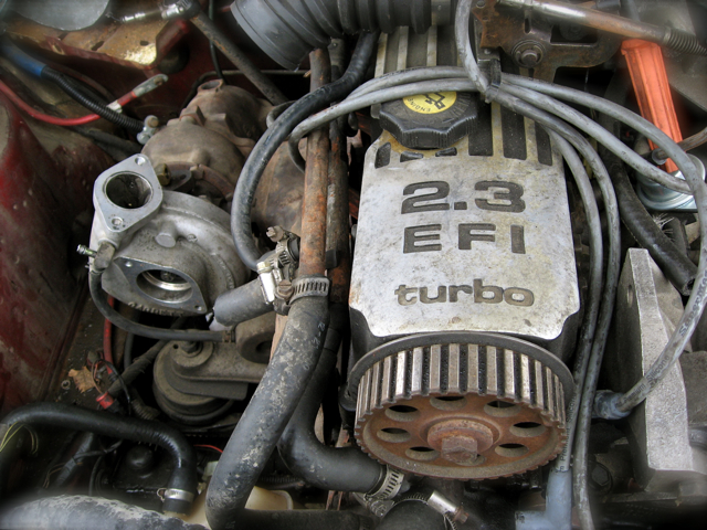
Timing belt slipped...setting timing on the Ford 2.3L Turbo

My Merkur left me on the side of the road a while back, but it was likely the timing belt tensioner  not creating enough tension on the timing belt which allowed the belt to slip. Given I needed to adjust the timing belt, I went in search of how to do it. Turns out while you do need to pay attention to how things are lining up, the process isn't that complicated.


  1. The pointer on the camshaft gear needs to point between the center of the cam bolt to the center of the auxiliary (distributor) shaft gear. 
  2. The crank has its own timing pointer, which goes from center of the crank to the center of the auxshaft. This sets the #1 piston to top dead center (TDC). As I understand, you can also, gently, put something in the #1 spark plug hole to determine if #1 is TDC by rotating the crank until you have the minimum amount of screwdriver inserted.
  3. Next is the auxshaft. The easiest way to set the auxshaft, which drives the oil pump and distributor gear and therefore the rotor is to just rotate the auxshaft which turns the rotor and get it as close as you can to the right position for plug #1. 
  4. Next is to put the timing belt on, maintaining full tension while working your way counterclockwise from the crank gear. 
    1. First, put the belt on the crank gear. 
    2. Next, pull it tight around the auxshaft.
    3. Third, remembering to maintain tension, pull it around the cam gear. ***You don't want any slack on the drivers side of the engine.***
  5. Now you can release the tensioner by loosening one or both bolts that have been holding it in place away from the timing belt.
  6. Slowly rotate the engine 2 revolutions by turning the crank to allow the tensioner to take up and remaining slack.  This is one of the leading causes of belts slipping on these engines. Don't be like me and make sure you do this. 
  7. Check the timing marks, one last time, making sure they're all lined up the way they should be and then torque down both of the belt tensioner bolts.


Wednesday, March 28, 2018

Anyone need a good start at a Merkur XR4TI build?

Craigslist find, in Anchorage, AK. Should anyone be interested in what would probably be a road trip to get it...seems like a number of solid choices were made in building this car up.


Triple black xr with rs500 pinstipes-rare option. Fresh build. New/upgraded everything. Hope to find this car a good home. intercooler install and exhaust work only things left to complete-very picky design phase on everything decided on. Tried n true parts combination/build. Been building this car with the picky/knowledgible buyer In mind. Meticulous mechanic. 

lets just say it was built for you. Price doesn't even cover cost of parts. I could drive it daily but I don't. 


  • Eng/trans break-In done In my 88 tc, under 10k miles.
  • Professionally built forged 2.3.
  • Ranger roller cam walsh adj-4.
  • T5 swap tc wc very low mi. new clutch.
  • Aerostar ds with haulsee adapter.
  • La3 ecm-no cuts-fact wire pin to pin. big vam
  • E6 60/63 garrett stinger stainless down pipe
  • Bosch o2, motocraft plugs/wires.
  • Rear mounted yellow optima batt. Upgraded grounds.
  • 16x7 svt contour baby cobra rims w/svt caps.
  • 10k on 205/55/16 bfg sport comp 2 z rated tires.
  • upgraded ranger wheel studs. 
  • 1g dsm bov/bpv and intercooler. (To be installed)
  • Cd/usb amp box.
  • 1988 xr-150mph dash/wide tunnel. 
  • Bi wing hatch- comes with single wing orig also.
  • Difficult Zero footprint type build-factory feel throughout a much improved car.
  • Cosworth grille, vents and lights with correct bulkheads
  • runs flawless-setup spot on. Never turned up-fact cntrl
  • Well balanced world class touring car-88 wtc champ.
  • Much more new/Improved than listed.
  • Not car show nice-enough to hold its own in parkin lot.
  • Cleanest xr you'll find. No leaks/drips. Runs smoother than a new xr. Original paint no touch ups. Comes with hp build parts and titled parts car.
Need to take some new pics. Lots of little things completed before winter-None like it in [Alaska]. Clean title good tags. $3000 to the right person.


https://anchorage.craigslist.org/cto/d/88-xr4ti/6513620743.html

Wednesday, March 21, 2018

A Brief History of the XR4Ti: The Inside Story

First off, this isn't my work, it's reprinted here, with permission from ClunkBucket. I thought this was a good write-up of how this car came to be, from someone who was at Ford Motor Company (FoMoCo) when it all happened. Enjoy! --Chris

A Brief History of the XR4Ti: The Inside Story


Ford of Europe, from about 1975 on, was considered a training ground for Ford Motor Company’s highest-potential executives, engineers and designers. Succeed over there, in that cauldron of competition against Fiat, VW, Renault, Peugeot-Citroen and GM, and you MUST be smart! Or willing to work 20 hours a day, and seven days a week. That was the thinking.
Over the long haul, Ford of Britain and later Ford of Europe had sent cars to America, starting in the 1950s with the Consul and Anglia, and later the Cortina, Capri, and Fiesta, but with each succeeding car program, it got more expensive to Americanize or federalize each car, narrowing profit margins and chewing up valuable engineering time.  But, if a high-volume car could be Americanized and federalized successfully, the program might be enough to punch somebody’s ticket on the train to the top.
One of the Engineer/MBAs who had had a successful run at Ford of Europe was Donald E. “Pete” Petersen, who by March of 1980 had been named president and CEO of Ford Motor Company.  He was a tall, slender ex-Marine officer, and he had seen a great deal that he liked while working in Europe.
In 1982, the car design world got a big shock with the introduction of the Audi 100, called the 5000 here. It was the first full-on aero production car the world had seen since the Chrysler Airflow in 1934, with flush glass, aero mirrors and a shape that would draw the eye like Madonna or Cindy Crawford, at the time.
Not too long after that, Ford introduced the Sierra, a production car based on the Probe III concept vehicle develop by Ford and its Ghia studios in Turin, Italy, introduced in 1981.
Sierra was a whole new line of mid-sized cars designed to replace the Taunus and Cortina. Sierra came as a 5-door hatchback sedan and a station wagon, with a grille-less front end, pulled-in fenders, flush headlamps and a rounded roof. A three-door coupe came a year or so later. Some Americans thought Sierra was a rip-off of the Audi, but even a cursory glimpse shows that the two cars are not at all alike. The XR4i, the performance coupe version of the Sierra, with its bi-wing rear spoiler and big, thick, forward-leaning C pillar, looked like nothing else on the road.
The Sierra sold in Europe with a wide range of 4-cylinder gasoline and diesel engines and a 2.8-liter Cologne V-6, but did not excite the market at first. Some versions were available with all-wheel-drive, called XR4X4, and in South Africa, the car could be ordered with a 302 V-8, and was called XR8.
The Ford of Europe boss was a guy named Bob Lutz, who would later return to Ford North America to run the truck business, then on to Chrysler, then General Motors. The chief designer at the time was German ace Uwe Bahnsen, assisted by Frenchman Patrick le Quement.  Sierra would ultimately be produced in England, Germany, Belgium, South Africa, Argentina, Venezuela and New Zealand. It was produced in a huge number of variants over a ten-year period, and made a great deal of money for Ford.
In North America, Ford was enjoying the success of the small Tempo and Topaz and the first of the aero Thunderbirds, selling tons of trucks and Town Cars for huge per-unit profits, and contemplating the rest of the 1980s. Ford’s racing organization, formalized in 1980 as Special Vehicle Operations or SVO, was headed up by German racing executive Michael Kranefuss, and part of his job was to create exciting street cars from the parts on hand.
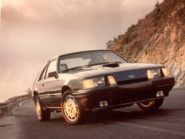
SVO’s first attempt at that was the Mustang SVO, using a turbocharged version of Ford’s cooking 2.3-liter engine, fitted with electronic fuel injection and an big intercooler, with tire, brake and suspension upgrades to match its 175 horsepower output and an offset functional hood scoop that would help it look different from the Mustang GT V-8.
Naturally, the Lincoln-Mercury dealers would have liked something hot like the SVO to sell, but there wasn’t anything in the plans.  Until someone high up in the company suggested bringing the Sierra XR4i coupe into the U.S. and using the same 2.3-liter engine as the SVO carried, without the expensive intercooler. Someone. Okay, it was Bob Lutz.
The U.S. car would have a cool, driver-centered dashboard and instrument panel, leather seating for four, lower body cladding, and a red stripe in the cladding. The underpinnings would be largely left alone. The featured color would be silver. So, the plan was to hire an outside firm, namely Karmann of Germany, to build the 2.3 turbo-powered Sierra XR4Tis, to give the cars some handbuilt panache and to take the production headaches out of Ford’s existing production system. The plan gathered momentum quickly.
At one point in the program, though, it was suggested by no less a personage than Edsel Bryant Ford II, who was then the marketing guy at Lincoln-Mercury Division, that perhaps a South African-style 302 V-8 might be a better way to go, and at his direction, Ford built two prototypes using the latest version of the U.S. 302, one manual and one automatic. After some fairly rigorous testing, during which the cars proved too nose heavy and cumbersome for comfort, the company went back to Plan A.
But there was a problem. The car couldn’t be sold as the Sierra in North America because GMC had been using Sierra for pickups for years and Oldsmobile had introduced a Ciera version of the Cutlass in 1982, and by 1985, the scheduled introduction year for the new Ford of Europe car, the name, spelled differently but pronounced the same, would be a marketing problem.
The problem trickled its way all the way up to the top of the company, to the product committee, and it was decided very quickly by Pete Petersen, the CEO and Ford of Europe veteran, that the car would be called the Merkur XR4Ti, using the German word for Mercury as the brand name, and adding a capital T for turbocharging to distinguish the car from the European XR4i.  Now I ask you, who was going to argue the name with the CEO in those meetings, especially an ex-Marine whose nickname was “The Smiling Cobra?”
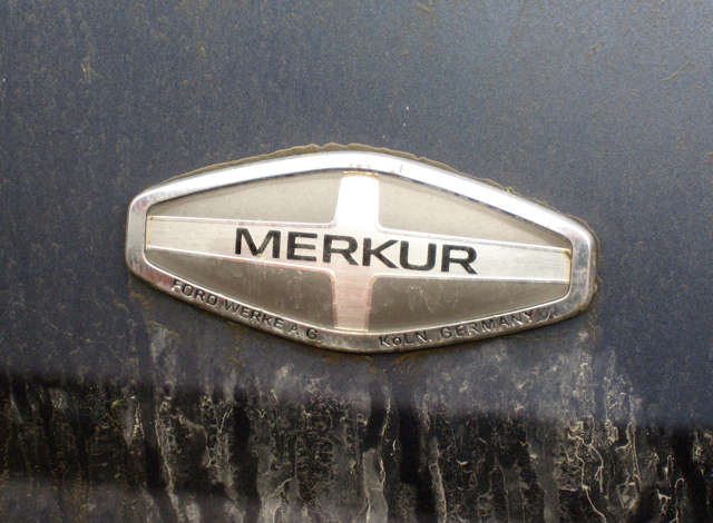
It was further decided that a new silver-and-black Merkur logo would be designed for use on the nose and tail of the car, and that every Lincoln-Mercury dealer who signed up for the new Merkur franchise would add one or more of these logos to his dealership signage.  Nearly everyone who was presented with the name early on in the program had no idea what the name meant, nor how it was pronounced in German, usually pronouncing it MERKer.
Would the entire program have been better off if the car had simply been called the Mercury XR4Ti?  It had worked previously with the German-built Capri, and would work again with the Australian-built roadster, but this time, it was to be Merkur, because the boss said so.
As the production, sales, franchising and marketing pieces started to come together into a master plan, the Ford Product & Technology Public Affairs team was called in to plan and execute the launch of the new Eurocar to the American and Canadian automotive media.
How about this? we said. How about we get a European driver to help us introduce the car to the media? How about three-time Formula One world champion Jackie Stewart?  He was already shilling for the company on a number of fronts, everybody knew him from his racing and broadcasting careers, and if he told the media the car handled great, who would dare challenge him?
Jackie, at that time, got US$5000 per day, plus first-class round-trip air fare from his home in Switzerland, including crossing the water on the supersonic Concorde. This was going to be expensive!
A small handful of XR4Tis arrived from the assembly plant in Germany, and they were examined inside and out by Ford’s crack team of press-car preparers at their shop on Michigan Avenue.  Everything on each car was “optimized” for best performance, and each car was test-driven by a handling expert from SVO.
The invitations went out, and the responses came back.  Every car magazine worthy of the name at that time would get a chance to drive the car. No websites, no bloggers, just ink-stained wretches from half a dozen top car magazines. No lifestyle journalists, nobody from the business magazines.
It was further decided that for the media launch, Ford would use the gigantic proving grounds north of Detroit at Romeo.  It had enormous elevation changes, a five-mile oval for high-speed testing, two long straightaways, and a very challenging and hilly road course, a far cry from the relatively flat and dinky test track in Dearborn.  Hotels, airport transportation, tents, catering, and the cooperation of the Romeo staff (meaning put away all the other prototypes for the day so the media can’t see them driving around) were all arranged.
When the magazine reports came out, the Merkur XR4Ti got pretty much rave reviews for its zoomy styling, good power, good seats, and very good handling. The 0-60 mph times were all in the low-seven-second bracket, the magazine mavens seemed to be satisfied, and the Merkur brand was well and truly launched in the US of A.
Later on, when the magazines each got their own Merkur XR4Tis to test on their home tracks, most of them noticed a considerable deterioration in acceleration performance, and the fall-off was duly noted in the later stories.  Apparently the careful preparation of the engines and turbo systems (okay, full-on blueprinting) in the small fleet of launch cars used on the Jackie Stewart program had come around and bit us in the ass.  Still later, some quality issues came up, and there were a few recalls here and there.
In that first year on the market, only about 9000 cars were sold against an annual financial planning volume or FPV of 20,000 units.  Between 1985 and the XR4Ti’s last year, 1989, fewer than 45,000 units were sold, and the program was stopped.
The next car in the new line was a complete departure, a luxury sedan, the Merkur Scorpio, based on the Ford of Europe Scorpio and sporting a 2.9-liter V-6 engine that was far too small and weak for such a heavy luxury car. It was a dismal failure in the U.S. in spite of its excellent exterior and interior design. By 1990, the dealers who had signed up were taking their signs down.
Some 20 years on, after three abortive attempts to bring the Ford worldwide design and production network together into a cohesive, productive whole, the Boeing outsider, chairman and CEO Alan Mulally, has finally done it, creating One Ford from the ashes of all the previous programs, and the new Fiesta is the first fruit of that Europe-to-America-with-no-changes idea. We shall see what happens now.
About the author. Jim McCraw was editor of Super Stock & Drag Illustrated, editor of Hot Rod, and executive editor of Motor Trend.  He worked for Ford Motor Company between 1983 and 1990 as a product launch and motorsports specialist, including a 2-1/2-year stint at Ford of Europe. During that time, he helped to launch the aero Thunderbird, Tempo and Topaz, Taurus and Sable, Mustang SVO, Lincoln Mark VII, the Australian-sourced Mercury Capri, the Merkur XR4Ti, Sierra Evolution I, Sierra Sapphire, the Sierra-based P100 pickup truck, Sierra Cosworth, Ford Scorpio, and Ford Fiesta.